INSTALLATION INSTRUCTIONS PART NUMBER 24
These installation instructions have been developed for the installation of Ashby Glare Shield Model 24. The Glare Shield has been designed to fit all Comanche aircraft, including the twin engine models. Refer to the STC for specific application information.
As each aircraft is slightly different, some trimming may be necessary for the proper fit. PLEASE TAKE THE TIME TO READ THE INSTRUCTIONS BEFORE ATTEMPTING INSTALLATION.
Pre-installation:
1. Remove plastic trim from the windshield posts on both the left and right sides.
2. Protect the inside surface of the windshield from scratches. Using plastic tape or other suitable material.
3. Remove old panel cover, including defroster louvers, handholds, or other items mounted to the top of the instrument panel.
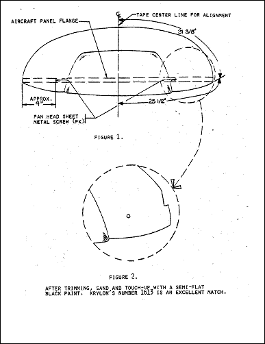
4. Find the center of the glare shield by measuring from the right and left corners, front and rear. (See figure #1). Place a piece of masking tape from the center front to center rear of the glare shield. Mark the center of the aircraft instrument panel with tape.
Glare shield Trimming
5. Perform a rough fit of the glare shield. Place the right side of the glare shield past the post on the right. Bend the glare shield just enough to slide the left side in and forward of the left post. Caution: Hold the forward edge of the shield against the panel top so it will not rub and scratch the windshield!
6. Center the glare shield on the panel top and mark the post area to be notched. (No notch will be required if a one-piece windshield has been installed).
7. If your aircraft has the flexible metal hose (1960 or earlier) remove the tube end and spring clips from the old panel cover and install them on the new glare shield.
8. If your aircraft has the defroster louver (1961 or later) the louver should be centered over the hole you cut in the new shield and pop-riveted on. (Note: mount the pop-rivet from the bottom so the glare shield will not rest on the rivet stems).
9. It will be evident at this point that the windshield actually rests on the aircraft instrument panel at the sides; therefore, trimming the glare shield is necessary. A small notch (similar to that shown in Figure #2) should be removed. Please, do not try to force the right or left sides between the windshield and the instrument panel as you could break the glare shield or the windshield. Trim only that amount necessary as this trimming may show from the outside, above the windshield band. The glare shield should rest on the instrument panel and around the front by the windshield. By design and for radio cooling, when properly fitted, it will be from Ľ" to 3/8" above the instrument panel at the center.
Note: If you have a 260 or a twin Comanche, some trimming will be necessary around the fresh air vents at the extreme right and left of the instrument panel.
10. Install the glare shield and take measurements to locate the existing tinnerman clip or nut-plates in the left and right corners of the original center panel.. If you have a large enough HOLE FINDER use it to locate the same and drill a 1/8" hole through the glare shield. (see figure # 1). Use original screws to secure the glare shield.
11. If you have a magnetic compass mounted on your panel top, you can remount it as it was on the original panel cover; FAR part 43.13 1A will provide the size and space of the reinforcement plate.
12. We also recommend that you contact your radio technician and ask his advice as to proper cooling for your particular radio installation. Slots can be cut in the glare shield top if absolutely necessary.