INSTALLATION INSTRUCTIONS PART NUMBER 28, PART NUMBER 6, AND PART NUMBER 180.
These installation instructions have been developed for the installation of Ashby Glare Shield models 28, 6, and 180. The part number 6 is applicable to the Piper Cherokee 6, Lance and Seneca aircraft.
The part number 28 is applicable to all Piper PA 28 aircraft, except the early 150, 160, 180 or 235 between the years 1964 to 1967.
The part number 180 is applicable to the early 150, 160, 180 or 235 between the years 1964 to 1967.
Refer to the STC for specific application information
Pre-installation:
EACH AIRCRAFT MODEL IS SLIGHTLY DIFFERENT AND SOME OF THESE INSTRUCTIONS MAY NOT APPLY TO YOUR SPECIFIC MODEL. SOME TRIMMING IS NECESSARY FOR PROPER FIT. PLEASE READ THESE INSTRUCTIONS CAREFULLY BEFORE ATTEMPTING TO INSTALL THE GLARES SHIELD.
It is not necessary to remove the windshield to install the glare shield. However, it makes the installation convenient and saves time, especially if you are working alone. Piper has made windshield removal easier by the use of nut plates.
It is not possible to install the glare shield in the early 150, 160, 180, or 235 (1964-67 with the large hump over the radio stack) without removing at least the right side windshield (part number 180).
1. Remove the handhold, defroster louvers, compass (if mounted on top of the panel), and fabric. Inspect the top of the instrument panel for any corrosion or damage. Repair as necessary.
2. The cover on top of the instruments (plastic bezel) is shaped so that it protrudes toward the pilot, or tilts forward or slightly down. You have the choice of either cutting it off level with the top of the panel and removing it, or having the glareshield fit over the top of it.
3. If you have a model with a padded overhang, it will have to be removed. The outer corner, where the horizontal screws were removed, may interfere with the way the glare shield sits and you may need to file the metal down to allow the glare shield to fit on top of the instrument panel sheet metal.
Glare shield Trimming
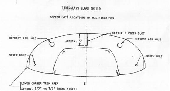
4. Make a paper pattern from the Ashby fiberglass glare shield. Place this pattern on top of the aircraft instrument panel and locate the windshield center post and the defroster holes. A slot must be cut for the windshield center post. Mark this slot on the paper pattern 5 inches long by 1” wide (see drawing). The outboard corners of the glareshield will need to be trimmed approximately ˝ to ľ inch to prevent the installed glare shield from contacting the windshield. Measure this trim line and mark it on the paper pattern.
5. The recommended method for trimming the fiberglass glare shield is to use an air die grinder with a thin fiberglass abrasive cutting disc. Mark the cutting line with a grease pencil. For round cuts use a standard drill bit or Unibit.
6. Trim the glare shield according to the pattern you have made.
7. Attach the defroster louvers over the defroster holes you cut by aligning the trailing edge of the new glare shield with that of the louvers. Use Ľ” long by 1/8” diameter pop-rivet installed from the UNDERSIDE of the glare shield so that the rivet stems will not hold the glare shield off the instrument panel.
Installation
8. If your windshield is still in, remove the plastic post covers on both sides to prevent them from being damaged or marked.
9. Getting the new glare shield in and out can be challenging since it is wider than the window posts. There is a potential for damaging the lower corners of the windshield. Therefore it is a good idea to use small pieces of heavy plastic placed in the lower corners of the aircraft windshield in order to prevent scratching the plexiglass.
10. Place the left corner of the glare shield in front of the left windshield post. Bend the glare shield just enough for the right corner to clear the right windshield post. Push the fiberglass glare shield forward under the inner riveted windshield strap as far as possible.
Make sure the radius of the glare shield matches the radius of the instrument panel.
11. The optimal way to attach the glareshield is to use a self tapping sheet metal screw (PK) to hold the glareshield in place. One screw on each side where the glare shield rests on the panel should be sufficient. As an alternate, you may use Rivnuts or equivalent. In all cases you must be careful not to damage any structure or instruments. The recommended placement of the attachment screws is shown in Figure 2.
12. If your magnetic compass was mounted on your old panel top, you can re-mount it on the new glare shield using the same hardware and same location.
Figure 1 – Glareshield Installation
Figure 2 – Recommended Screw Placement